
Designing Small Wire EDM Features That Can Be Made and Measured
Published: 10.NOV.2026



Shrinking a component does more than shrink its drawing. A radius that looks negligible on a large plate may occupy most of a tiny slot. A clamping force that safely holds a conventional part may distort a delicate flexure. Even a visible edge can be difficult to measure consistently when its size approaches the limits of the chosen optical setup. Micro wire EDM projects succeed when manufacturing and measurement are planned together.
This article concerns sourcing small conductive parts and features, rather than purchasing EDM machinery. It follows the design decisions that an engineer can control: geometry, entry access, support, surface requirements and acceptance. The useful question is not how small a machine can theoretically cut, but whether a supplier can produce and verify the specified feature in the actual material and thickness.
Distinguish the process family from the feature
The term micro edm machining covers more than one electrode arrangement. Small wire-cut profiles, drilled features and shaped cavities can demand different methods. Jucheng CNC Machining's micro wire EDM guide focuses on wire-based processing and its applications. Use that distinction when sending an inquiry so the supplier receives a clear description of the required part, rather than an ambiguous process label.
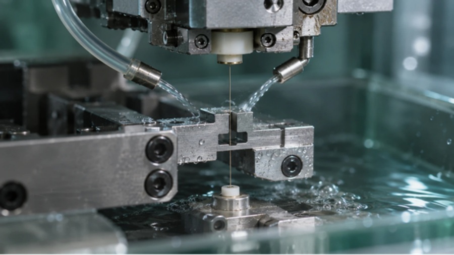
Wire EDM removes conductive material across a controlled electrical gap. The wire itself has a finite diameter, and the effective cut also includes the process gap. Those facts limit internal radii and influence slot design. A thinner wire may create opportunities, but it also changes process stability, handling and the relationship between cutting speed and feature requirements.
Specify the material and its final condition before asking about the minimum feature. Thickness, geometry and the required finish can change feasibility. A result demonstrated in a thin coupon should not automatically be transferred to a thicker component with different flushing access or thermal behavior. Request evidence relevant to the actual geometry whenever the design approaches the supplier's practical limits.
Read a tiny profile at full scale
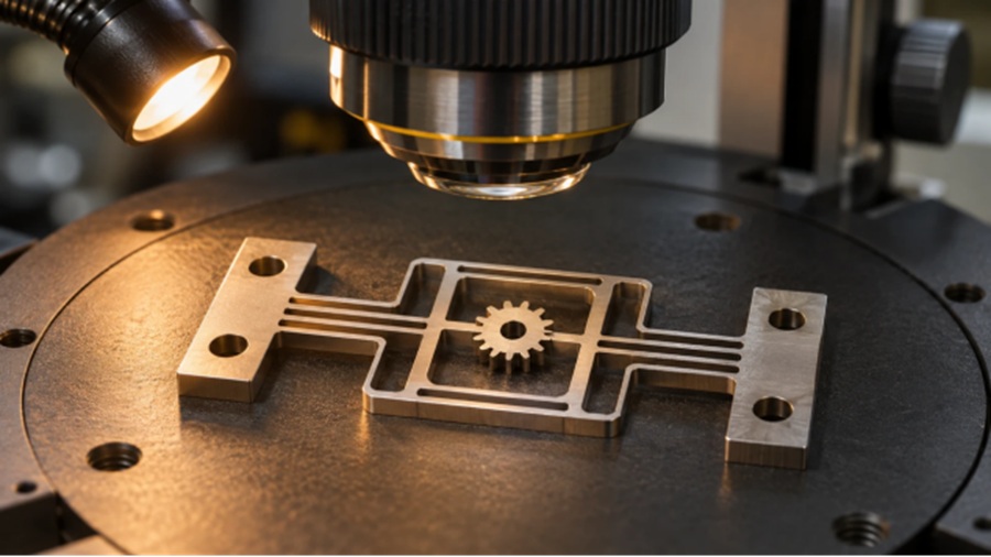
Begin a design review by showing the feature at its real size as well as magnified. Enlarged drawings help explain geometry but can disguise how little material remains between neighboring cuts. Mark the narrowest webs, smallest internal corners and features that must remain aligned after the waste material is removed.
For a closed internal profile, agree on an entry-hole strategy. The supplier must be able to create and reach the entry point without damaging the finished region. If the start hole lies in a discarded slug, indicate that clearly. If it remains in the part, its size and location become product requirements rather than incidental process details.
Do not specify a zero-radius internal corner as shorthand for a close-fitting interface. Determine the largest radius the assembly can accept. If the mating part can receive a small relief, the pair may become easier to manufacture and inspect. Design changes should be evaluated at the interface level, where the function is defined, rather than treating each component drawing in isolation.
Keep the part supported through the final cut
Low mechanical cutting force is useful for delicate parts, but it does not eliminate workholding concerns. Fixtures can distort thin sections, and material can move as residual stress is released. A tiny retained component or waste slug also needs a controlled release plan so it does not shift into the cutting path or damage a finished edge.
Discuss temporary support features, retained tabs or a machining sequence that preserves stiffness where appropriate. Any tabs need a defined removal method and acceptance requirement for the remaining surface. Buyers should know whether the supplier plans to deliver the component fully released or within a supporting frame for later handling.
Handling after machining can be as consequential as the cut. Tweezers, cleaning, drying and packaging may bend a delicate ligament or mark a contact surface. Define permitted handling areas and consider whether inspection should occur before and after a release or finishing operation. These details belong in the production plan, even when they do not appear in the headline capability description.
Design detail |
Manufacturing issue |
Measurement question |
Narrow slot |
Wire and gap must fit the profile |
Can the inspection method resolve both edges? |
Thin ligament |
Release or clamping may move it |
Is the part measured free or constrained? |
Internal profile |
Wire entry requires access |
Is the start feature part of acceptance? |
Tapered wall |
Top and bottom geometry may differ |
Which planes and angles must be recorded? |
Small corner |
Practical radius cannot be ignored |
Is radius evaluated directly or by functional fit? |
Choose an inspection method before promising a tolerance
Magnification is not the same as measurement capability. Edge detection, lighting, focus, calibration and the method used to establish datums can influence optical results. Contact probing has its own access and force limitations. The supplier should explain how each critical feature will be measured, particularly when the part is too small or fragile for conventional fixtures.
Specify whether acceptance applies in a free state or in a defined fixture. If a functional gauge represents the real assembly, explain what it proves and what it does not. A gauge that checks fit may not separately establish wall thickness or local profile error. Combining methods can be appropriate when different requirements need different evidence.
Agreement on a measurement method also reduces disagreements between incoming inspection and the supplier's report. Compare datum setup, environmental conditions and evaluation rules before rejecting a borderline result. The purpose is not to weaken a tolerance; it is to ensure both parties are assessing the same characteristic under comparable conditions.
Finish and function may pull in different directions
For wire edm cutting of small functional components, discuss finishing passes and surface requirements alongside geometry. Extra finishing may improve a particular surface characteristic, but it also affects cycle time and must be evaluated for the specific material and feature. Avoid requesting the finest possible finish everywhere unless the design actually depends on it.
Jucheng CNC Machining's technical coverage of wire EDM offers a relevant entry point for a drawing-based discussion of small precision parts. The purchasing value comes from connecting the feature to its manufacturing route and inspection plan. Confirm the available wire range, material experience and job-specific acceptance method rather than relying on a broad precision claim from an introductory article.
Thermal surface effects can matter in demanding applications. If the feature will flex repeatedly, contact another part or carry a critical load, identify the required surface condition and qualification evidence. Any polishing, deburring or cleaning step must preserve the geometry that justified using micro wire EDM in the first place.
Prepare an inquiry that a machinist can answer
Send a model and a drawing with the smallest features highlighted, material and thickness specified, and the functional interfaces explained. State quantities for development and anticipated production separately. Include whether the component must arrive loose, in a carrier or in protective packaging. If there is an existing mating part, provide its controlled interface information.
Ask the supplier to identify the limiting feature and describe the proposed support, entry and inspection strategy. A useful answer may recommend a small radius change or a different release sequence. Such feedback is often more valuable than an immediate yes to every dimension. Approve representative samples against the agreed method, then preserve those decisions for the production order.
Filed in: / Machines & Tools / Micro Wire EDM
Advertising